
1. Solutions for Welding Designs
In weld designing, the focus is on the geometric design options and selection of materials for each weld part. Very often, the positions of weld points and also the distance between weld points are also important to be optimized and determined in order to obtain the best quality of welded structures.
By welding simulations with SORPAS, the geometric designs of weld parts can be modeled with a flexible selection of material for any part with any material freely picked from the list of all materials in the integrated material database. In this way, all possibilities of geometric designs and material combinations can be simulated virtually on the computer. The optimal solutions of weld designs and material combinations can be obtained based on the results of simulations before running any weld tests with real materials and real parts.
We describe below in further details on the Weld Designing solutions for spot welding, projection welding and mechanical joining applications.
Spot welding design factors and weldability of materials
For resistance spot welding, the most decisive weld design factors are the following:
- Thickness ratio of the sheets
- Strength ratio of the sheet materials
- Resistance ratio of the sheet materials
- Surface coating properties and conditions
- Position of the weld close to edge or corner
Every time new material is introduced to production with welding and joining, a lot of investigations have to be carried out to evaluate the weldability of the material and the feasibility of implementing the material in production. From time to time, material suppliers may be changed even for ongoing production at the assembly plants. This often needs evaluation of the weldability of materials from the new suppliers in order to maintain weld quality and production stability.
SORPAS 2D.welding and SORPAS 3D.welding have been used as powerful tool to evaluate the weldability of materials with various ratios of sheet thickness and materials.
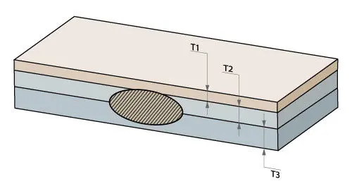
One of the most commonly encountered weldability problem in automotive industry is the three-sheet spot welding with a thin low carbon steel sheet and two thicker higher strength steels.
Publication on Welding journal 2011: Three-Sheet Spot Welding of Advanced High-Strength Steels.
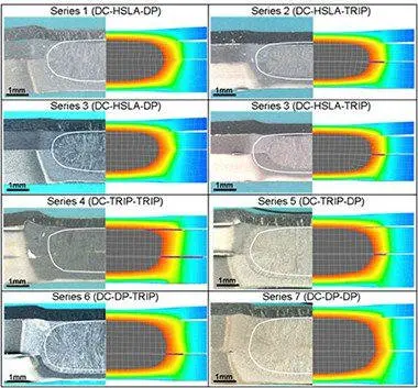
In recent years, SORPAS has been used to improve the resistance spot weld performance of 3rd Generation of advanced high strength steels (AHSS).
Conference paper on 11th International Seminar on Numerical Analysis of Weldability (2015):
Improved Resistance Spot weldability of 3rd Generation AHSS for Automotive Applications

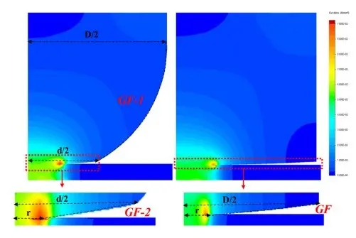
SORPAS has been also used to understand liquid metal embrittlement(LME) crack in welding of Zn-coated high strength steel. Many researchers use SORPAS to investigate the factors affecting LME during spot welding such as, temperature and stress at LME sensitive area. It also used to analyze the impact of electrode geometry and different weld schedule to prevent LME crack.
Related publications:
- Mechanical behaviour of a new automotive high manganese TWIP steel in the presence of liquid zinc
- Supercritical area and critical nugget diameter for liquid metal embrittlement of Zn-coated twining induced plasticity steels
- Liquid metal embrittlement-free welds of Zn-coated twinning induced plasticity steels
- Critical design parameters of the electrode for liquid metal embrittlement cracking in resistance spot welding*
Projection welding design factors and weldability of materials
Unlike in spot welding where the design of electrodes is important for concentrating the weld current to weld zone, in projection welding the design of projections on workpieces is essential to localize the current. The electrodes only supply the weld force and conduct the weld current to the workpieces.
The local projections on workpieces can be designed specially on purpose to concentrate weld current to the weld zone, such as embossment on flat sheet, ring projection on a round nut, or corner projections on square nut, etc. The natural shapes of the workpieces can also be used as projections to concentrate weld current to the weld zone, such as cross wire welding and fusing of round wire to a flat connector.
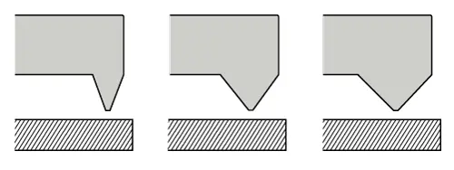
The design factors in projection welding are the shape, angle, and height of the projections. The design principle of projection welding is that the design of projections shall be effective to concentrate current, but be stable and not to collapse too fast or cause severe expulsions.
By effective concentration of current with projections on the workpieces, projection welding can be used to weld largely dissimilar materials, which may be impossible to weld by spot welding. By applying strategic surface coatings, it is even possible to weld extremely difficult materials by projection welding, such as copper alloy to steel.
Generally speaking, to obtain the heat generation with the best heat balance at the weld interface, the projection shall be placed on the side which is more difficult to produce heat:
- In case of similar materials, the projection shall be placed on the thicker workpiece due to larger volume and more mass to be heated.
- In case of dissimilar materials, the projection shall be placed on the workpiece of material with lower resistance.
- Likewise, the strategic surface coating usually with higher resistance shall be placed on the material with lower resistance.
The optimal designs of projections and the best choices of strategic surface coating materials, best fitting individual material combinations to be welded, can be simulated with SORPAS2D.welding for projection designs with symmetry, and more effectively simulated with SORPAS 3D.welding for more complex projection designs. The best projection designs can be obtained by comparing the simulated welding results with different designs and material choices.
Mechanical joining design factors and quality of the joints
Mechanical joining is widely used for joining dissimilar materials, and probably the only effective method for joining carbon fiber reinforced polymers to metals. Self-piercing riveting (SPR) and clinching are most commonly used for joining sheet materials in automotive industry.
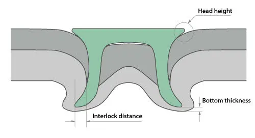
To achieve the best joint quality, engineers optimize rivet shape and material, die design and material, and tool force appropriately. The quality of the SPR joint can be evaluated by the key joint factors, for example, the interlocking length (rivet flaring), the minimum thickness of the bottom sheet, rivet head height, and effective length of the rivet in the bottom sheet.
SORPAS® 2D.joining can be used to simulate the mechanical joining with various designs and materials of rivets and dies for all combinations of sheet thickness and materials to be joined.
2. Solutions for Welding Process Optimizations
What is a process window?
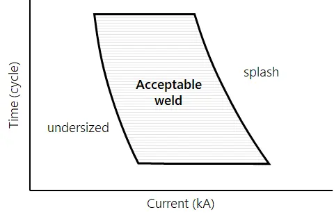
A process window represents the ranges of weld parameters, such as current, time, and force that will produce good quality welds.
The upper boundary of the process window is defined by the limits of expulsions/splashes. The lower boundary of the process window is defined by the minimum nugget sizes required for weld strengths.
Since the weld nugget by resistance welding is hidden between the sheets, it is difficult to verify the quality of welds by visual examination. Thus, finding the process window and using the right parameters is very important to maintain good weld quality.
Methods to find process windows
Due to the limitation of time and cost, many companies are running welding production with un-optimized parameters. They usually determine the parameters by trial-and-error tests, which can cause frequent production maintenance problems such as expulsions or poor welds.
It is necessary to find the process window for determining the right welding parameters.
A traditional way to find the process window is by repeating numerous physical weld tests with possible combinations of different weld parameters. There are ISO standards about the testing procedures for determining the weldability lobes and weld growth curves. This method is time-consuming and highly costly. When the availability of test materials and welding machines is limited, it is difficult to accomplish all tests and find the right parameters in time.
A faster and more cost-effective way to find the process window is by simulations with SORPAS®. After running a set of simulations, SORPAS® determines the process window. It has been used by many companies worldwide through many years to predict process windows and maintain good weld quality, especially for spot welding of all grades of steel sheets and aluminum alloys.
Find process windows by SORPAS®
In SORPAS, there are several automated functions for welding process optimizations to predict the optimal welding process windows.
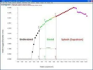
1) Weld growth curve
The weld growth curve represents the range of weld current that will produce acceptable welds. Since it only predicts the range of weld current, it is recommended for users who have enough knowledge about the reasonable values of weld force and time.
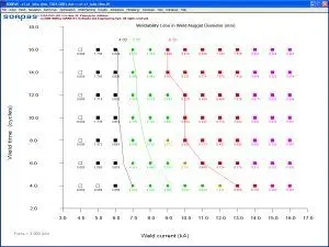
2) Weldability lobe
The weldability lobe represents the ranges of weld current and time or weld current and force that will produce acceptable welds. This is a more systematic way to determine the process window for a given weld combination. It gives an overview of more complete process possibilities.
Which parameters to choose?
To keep good weld quality, it is important to choose parameters inside the process window.
Even though all parameters inside the process window may produce acceptable welds, it is preferred to choose the weld parameters close to the splash limit. This is because there are always some dynamic disturbs during the production such as electrode degradation which could reduce the weld nugget sizes. Therefore the parameters close to the splash limit can be a safe choice for a more stable welding production and consistent weld quality.
The prediction of splash limit is one of the key strengths of SORPAS®. It is also essential for the advanced function of Weld Planning by SORPAS® 2D.welding to predict individually the optimal welding parameters for spot welding of different material and thickness combinations.
3. Solutions for Weld Planning

Excel Batch Planning
This function for Excel Batch Simulation can provide solutions for optimizing and planning of welding process parameters by directly reading input data from Excel datasheet files. Then it automatically makes simulation files and runs all simulations and optimizations. SORPAS puts all optimization results back to the Excel datasheet file. This will save a lot of time for the users to prepare simulations and drastically increase the productivity!
With this function, the engineers can maximize the benefits of simulations and optimizations, and substantially reduce the number of physical tests. Moreover, they can improve the weld quality and production stability with the support of massive and fast simulations and optimizations.
Intelligent Weld Planning
One of the mostly-used functions in SORPAS® 2D is the Intelligent Weld Planning for predicting the Optimal Weld Schedule (weld current, force, weld and hold time).
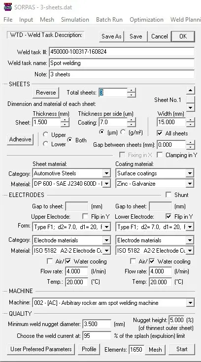
According to the user-defined Weld Task Description (WTD) with information of the sheets, electrodes, type of welding machine, and the desired weld quality, SORPAS® will automatically optimize and find the optimal weld current, force, weld time, and hold time.
The splash (expulsion) limit is predicted. Thereby SORPAS® predicts the welding process window between the required minimum weld nugget size and the splash (expulsion) limit.
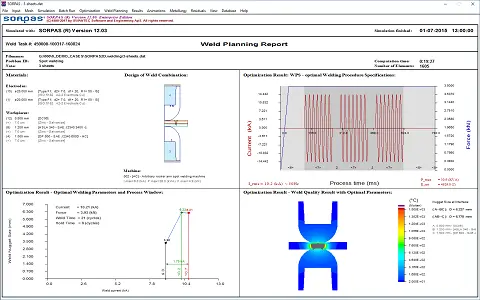
The Weld Planning Report will be finally produced with the below information.
- WTD information – sheets, electrodes, and weld machine
- Predicted optimal Weld Schedule Specifications (WSS) – the welding process window with optimal weld current, force, weld time, and hold time
- Weld Quality Results by the optimal welding process parameters.
SORPAS® Weld Planning Procedure
The SORPAS® Weld Planning works in the following procedure:
- WTD – Weld Task Description
- User Preferences
- Run Weld Planning to predict Optimal Welding Parameters
- Weld Planning Report with WSS – Weld Schedule Specifications
1) WTD – Weld Task Description is to define the weld task with specifications of sheets, electrodes, type of welding machine, and desired weld quality, see the figure to the right.
2) User Preferences are for user preferred planning strategy. SORPAS® will always optimize the weld current, but users have the freedom to choose their own preferred values for the weld force, weld time, or the number of pulses. You can either give a specific value or simply let SORPAS® fully optimize.
3) Run Weld Planning. After defining the Weld Task and User Preferences, you can start the Weld Planning. SORPAS® will then automatically run all the optimization procedures to first determine the optimal weld force and weld time, then to predict the welding process window and the splash (expulsion) limit, and finally to optimize the weld current and the hold time.
4) Weld Planning Report with WSS – the Optimal Weld Schedule Specifications is the results of the Weld Planning, which includes the given WTD, the predicted optimal welding process parameters (weld current, weld force, weld time and hold time), and the welding process window, as well as the weld quality results predicted with the optimal welding process parameters.
During the Weld Planning, all simulations and optimizations are done with only the same one data file. This substantially reduces the computation time and the use of hard disk space compared to the Weld Growth Curves and Weldability lobes.